
Hello World
A mechanical implementation of Conway’s Game of Life — the cellular-automaton algorithm, pursued first in wood and wire, and eventually in modern materials.
Sound concept
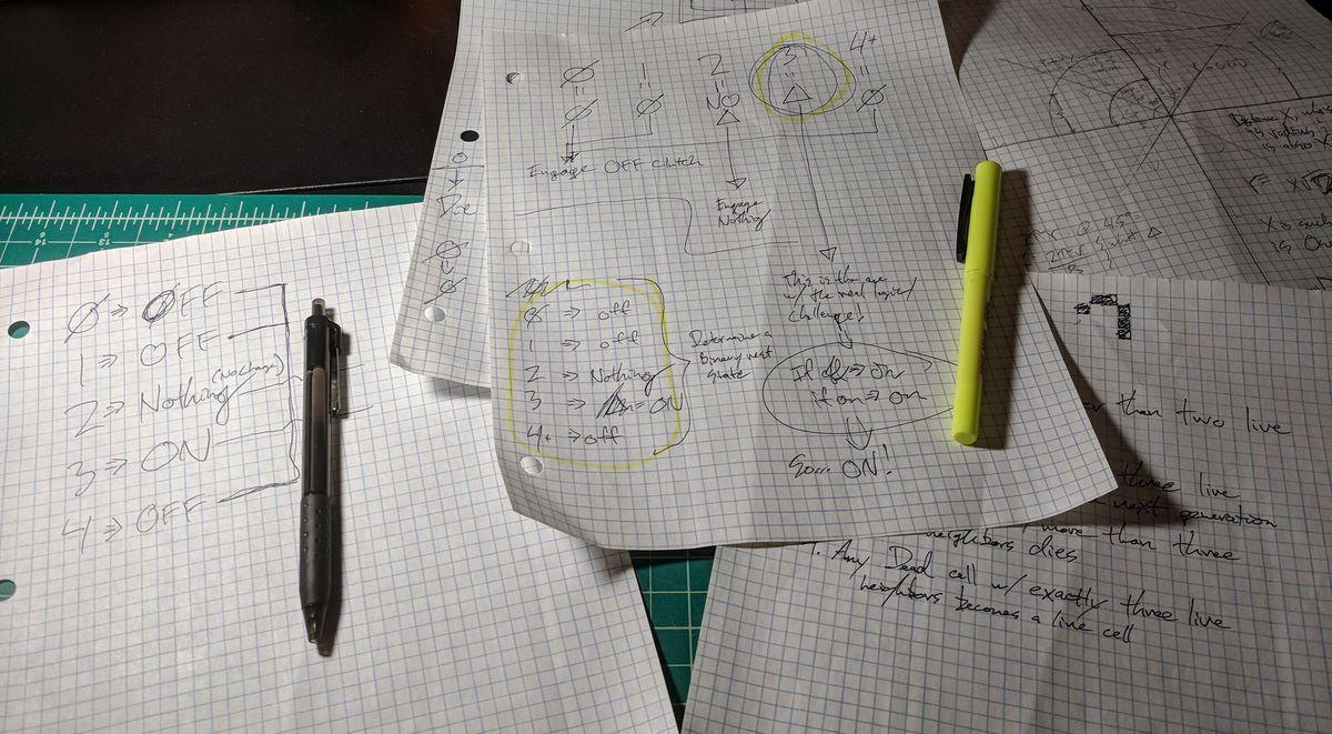
There are only a few revelations one needs to have to know it is possible to produce a fully mechanical implementation of the popular Conway's Game of Life. The idea came to me in college, and after years of experimenting and thinking, I found myself employed by a company that generated an almost boundless amount of scrap crate wood and wire hangers. So, those became the materials, and the evening hours became designing around "preexisting dimensions" and my available materials. After plenty of time at a wood lathe and router, it became clear custom parts with custom dimensions would greatly hinder the prototyping phase.
Substrate
This industrial-waste funded build starts out with an Oriented Strand Board cut into a square. Eventually, a complete grid will use dozens of these panels.
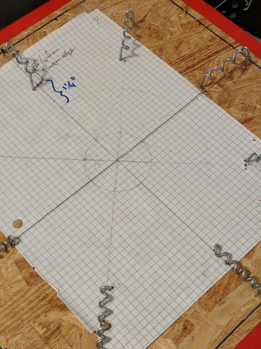
This thing is going to sound amazing
After some jigs and shapes were worked out, the input mechanism of the panel begins to sing.
Clocking wheel concept
This specific iteration of the GOL build utilized a mechanism that organized the machine's operation into a 10-count repetition of counting, evaluating and updating state.
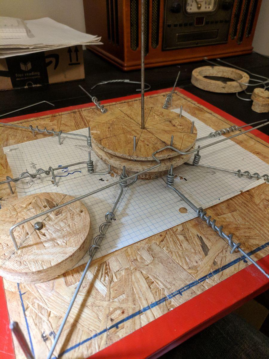
Fits of fits
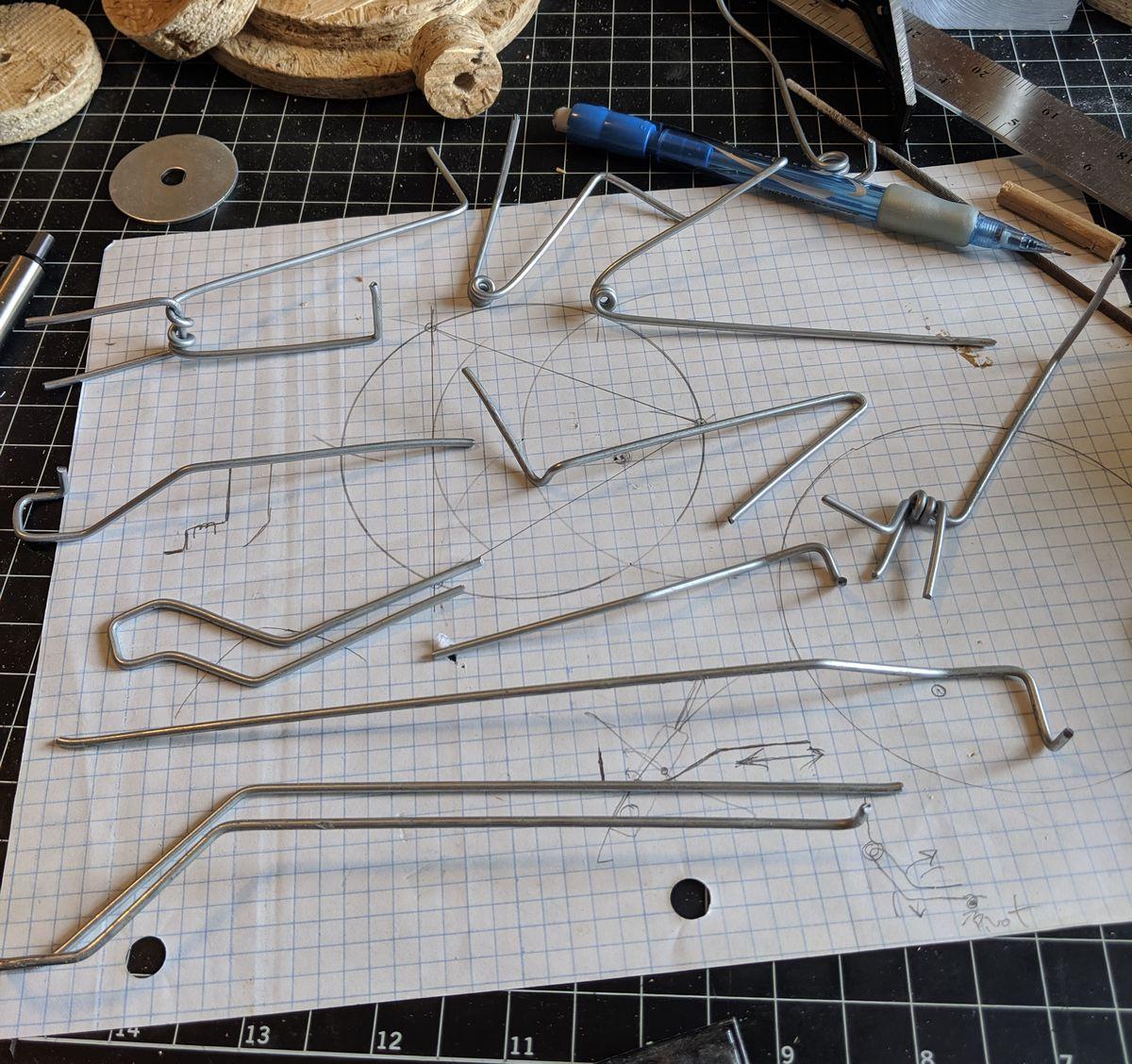
Designing movements that work in tandem without colliding with each other is a rather essential requirement to mind. All of the wire shapes pictured were constructed to solve the same problem, and none of these worked. Onto the next one.
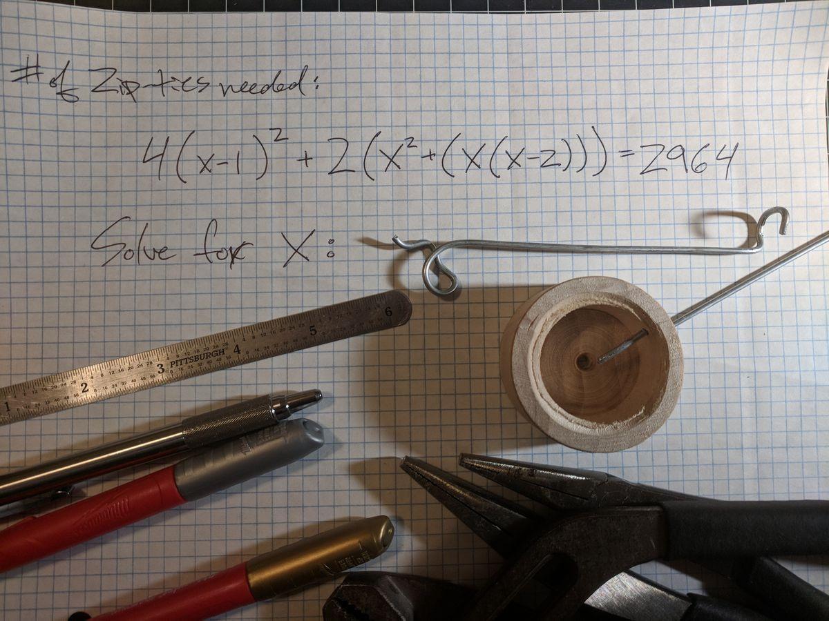
How many zip ties?
This equation represents the number of zip ties I would need for making all the required couplings for a grid of 20 panels x 20 panels. Here, expressed as a problem to be worked in reverse. Every now and again, I understand some real (albeit obscure) applications of what once seemed so abstract back in 7th grade.
Compass aided design
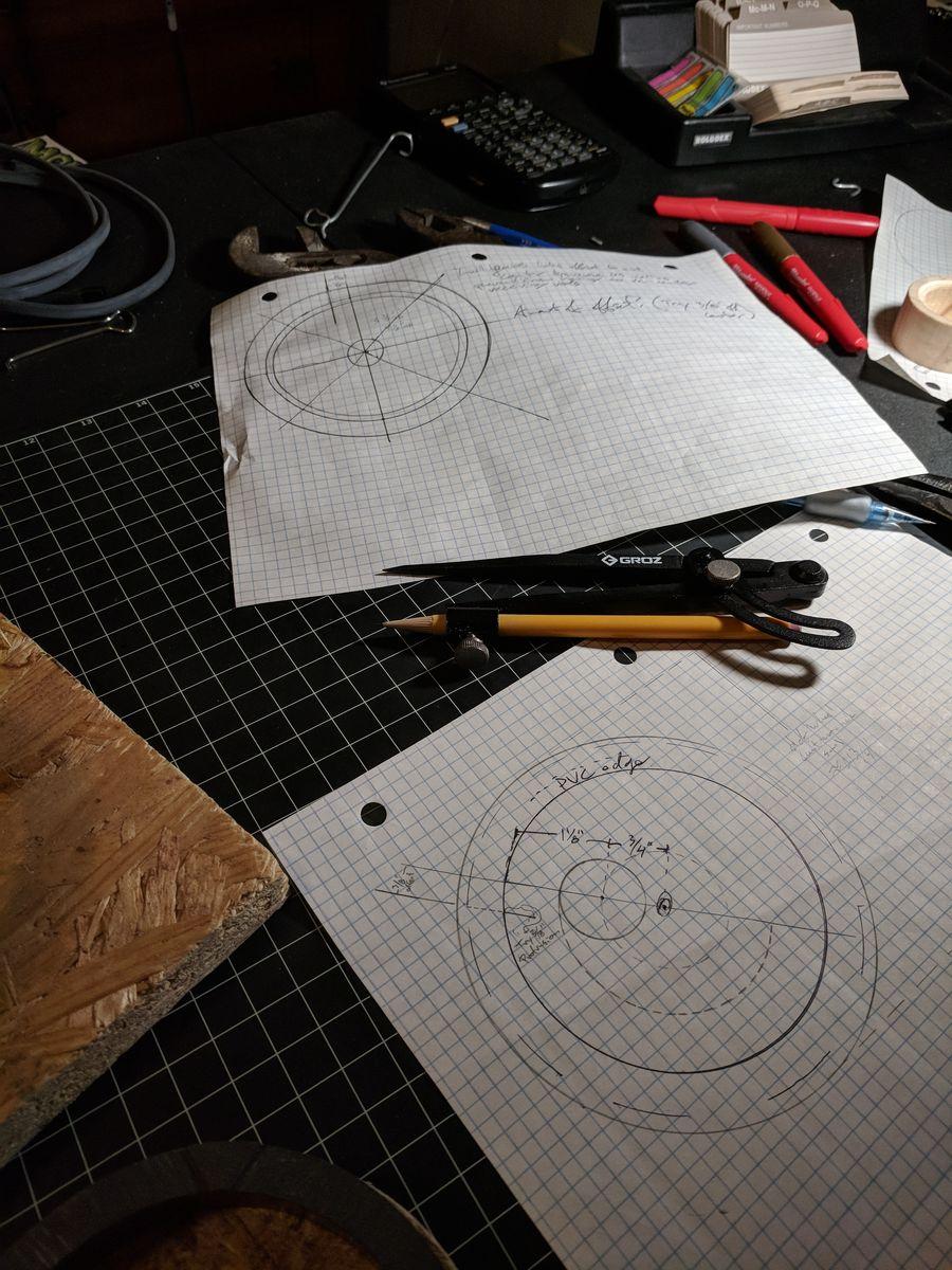
Much of the operation of interconnected parts was considered mentally and with the help of loose leaf graph paper, a pen and simple drafting tools (a compass and straight-edge).
Divide into 10
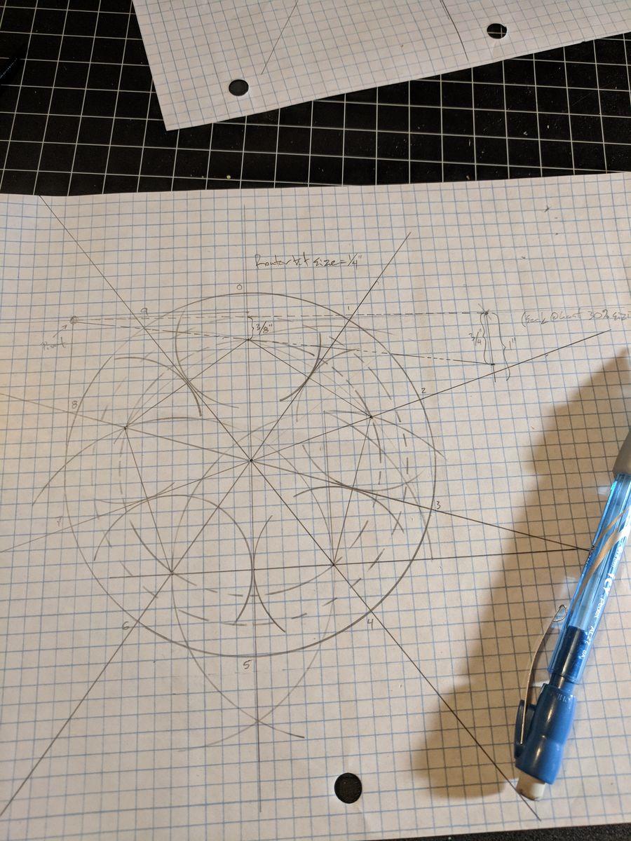
Since the piece works on a 10-count cycle, I became very proficient at laying out a circle into ten equal parts.
Gestation
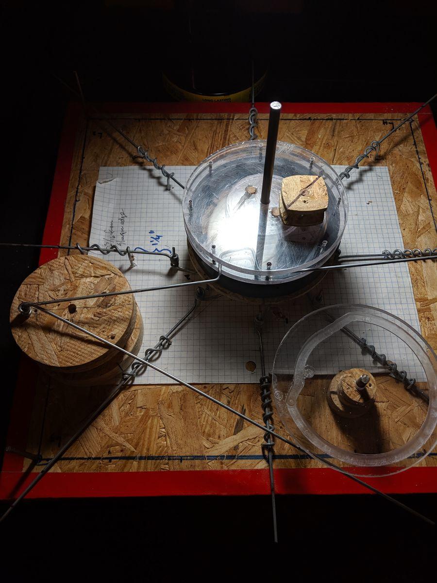
The Game of Life is coming to life. Note the plexiglass grooved cam. The groove was cut by using two different settings on a custom jig on a router. An additional jig was designed so I could hand-guide cuts to connect the two arcs without losing my hand.
Bustling surface
There is a somewhat architectural quality in the aesthetic being expressed here. The layers and layout of the board up to this point invoke images of a future city layout with large open spaces. However, the board will become more dense with time.
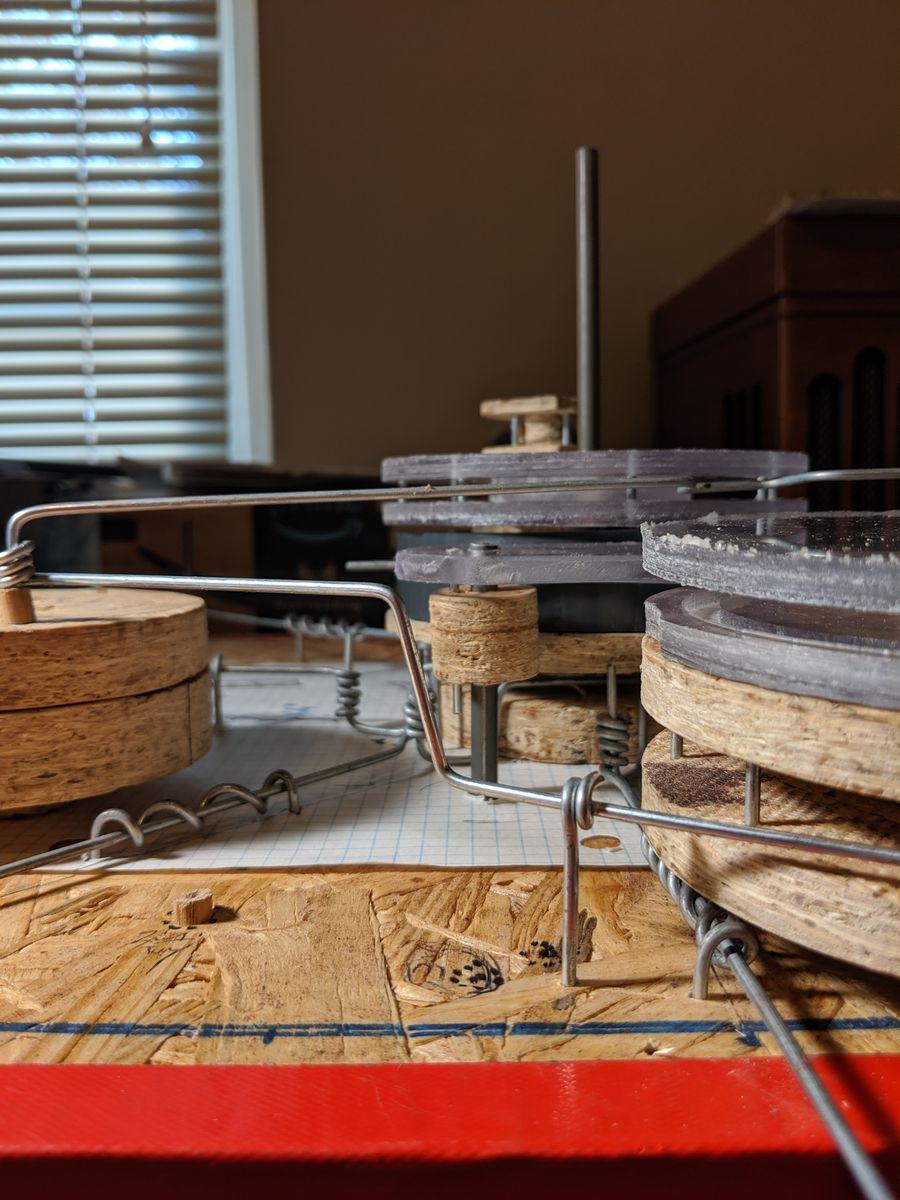
Count cycle and evaluation clutch test
Well, this is going well. We're getting closer; warmer.
Comms established
The movement of the near wheel moves a pin on its neighbor's input wheel to broadcast its own state. This is where things get exciting. This is also where location changes and the workshop contracts. No worries. Looks like 3D printers just became available.
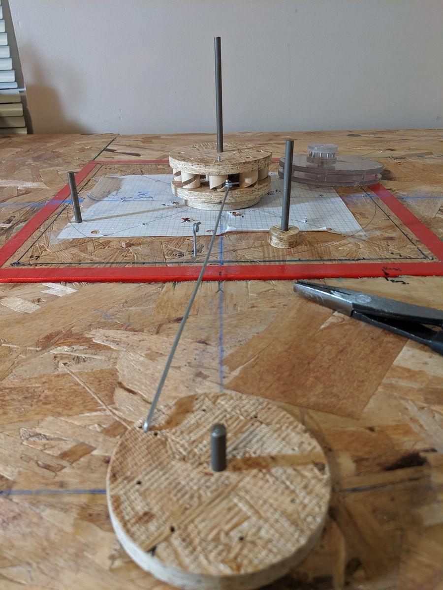
Eureka!
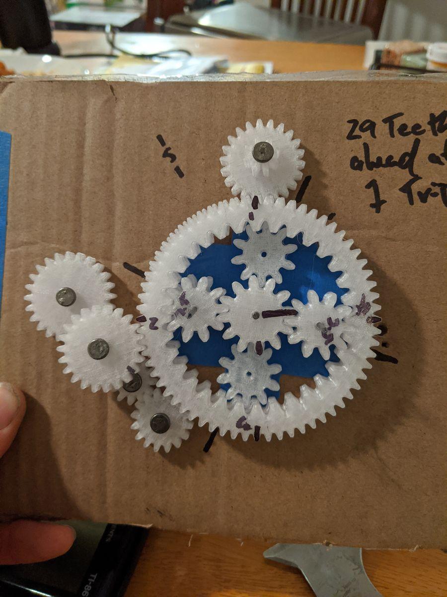
By the time of this image, I'd assembled a 3D printer and learned to operate computer aided design software in order to design parts to be printed with the 3D printers. I had also normalized the habit of keeping a notebook at the bedside. I had been sitting with the notion of a more efficient way of performing the count, and BOOM. I drew a rough, 2am version of this layout, and by the power of 3D printing + CAD I had a working demo in less than 24 hours.
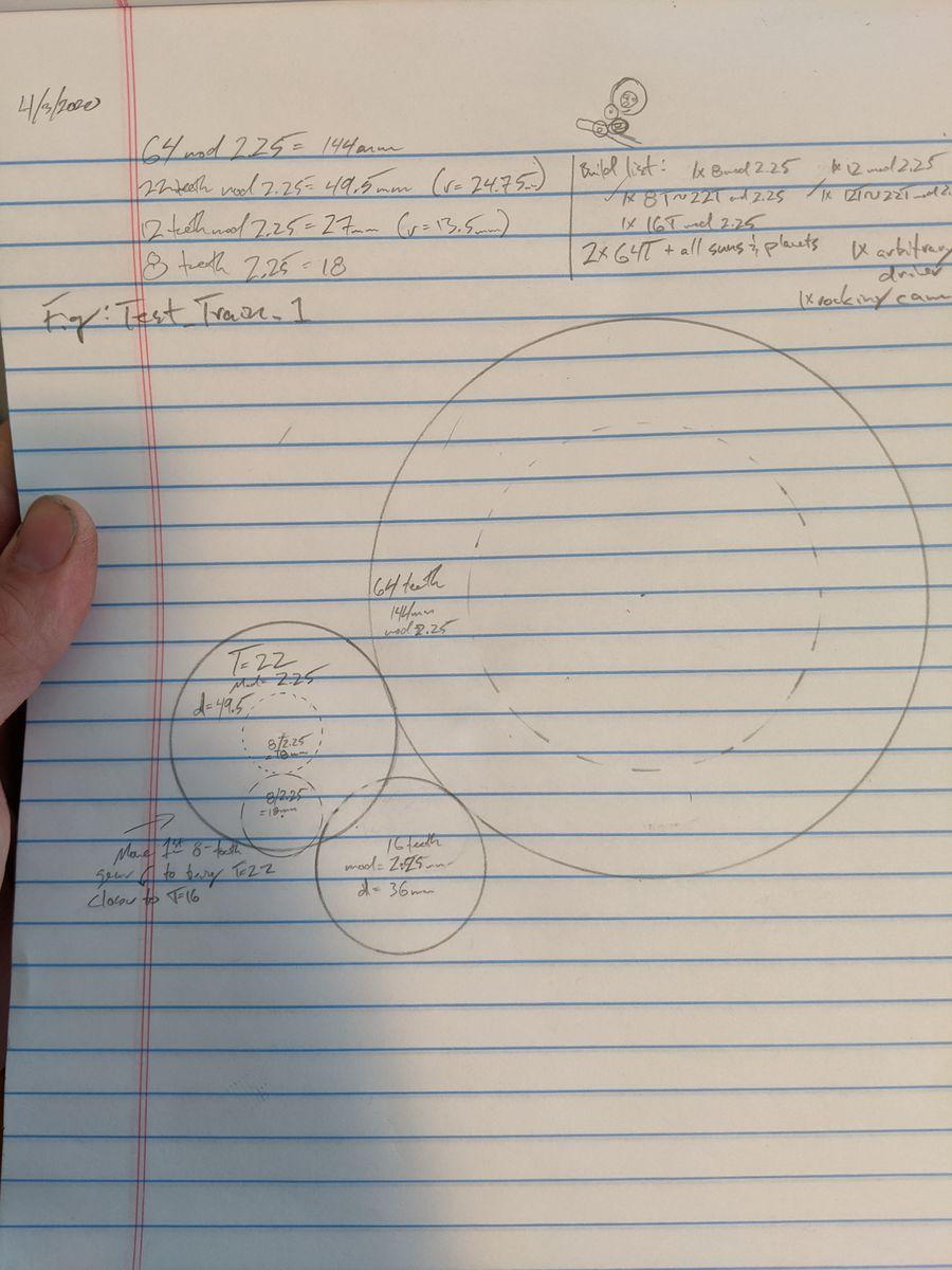
Sidequest
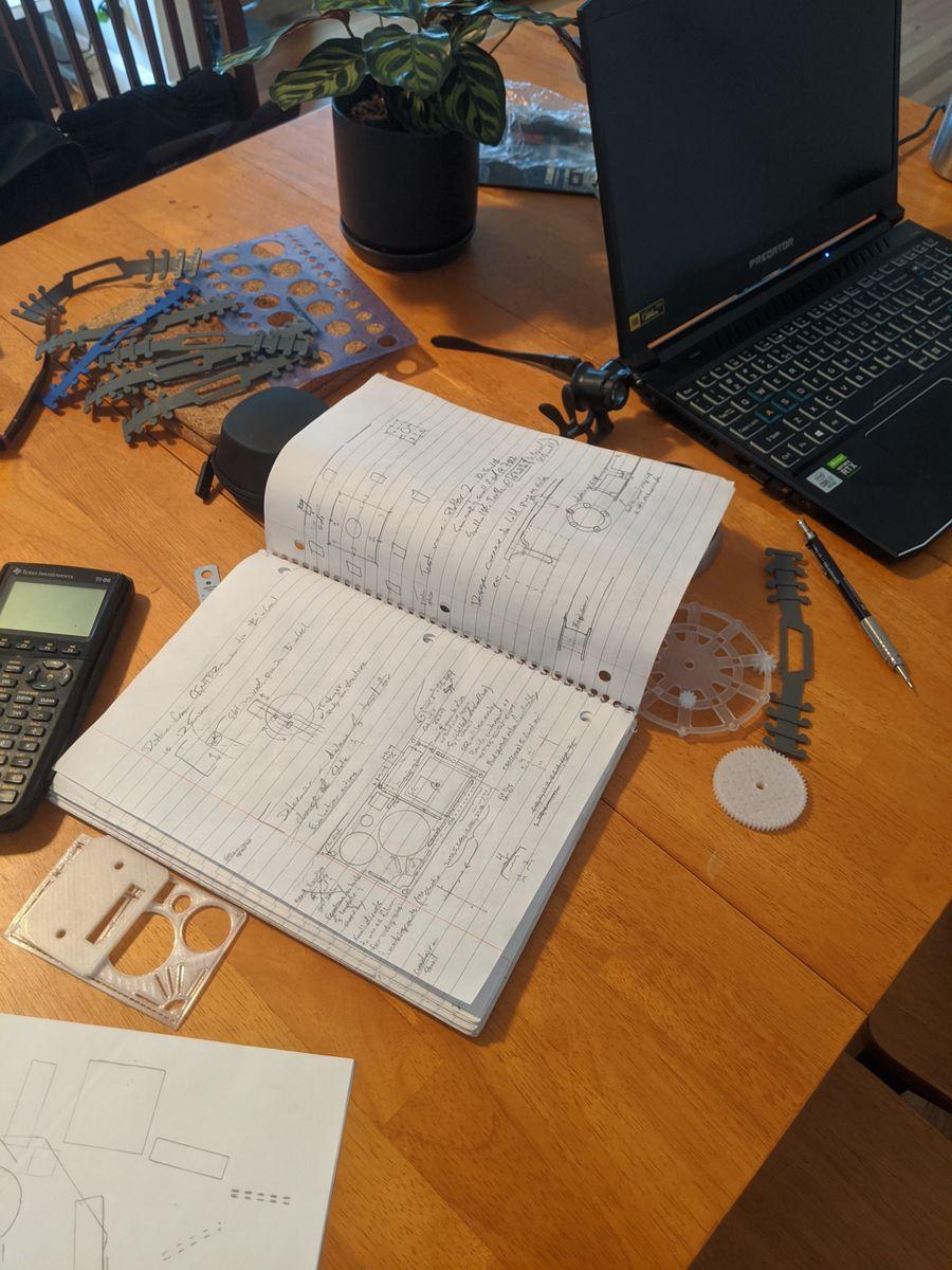
After years of drawing in notebooks and experiencing certain repeated idiosyncrasies in how I relate to design, a very useful template occurred to me. The design is pictured in the notebook, and a prototype can be seen under another part beside the notebook. This has been a long term project. Note one sign of the times... the 3D printed face-savers which were popular for relieving stress on the ears of all those required or choosing to wear a mask.
Totally new design direction
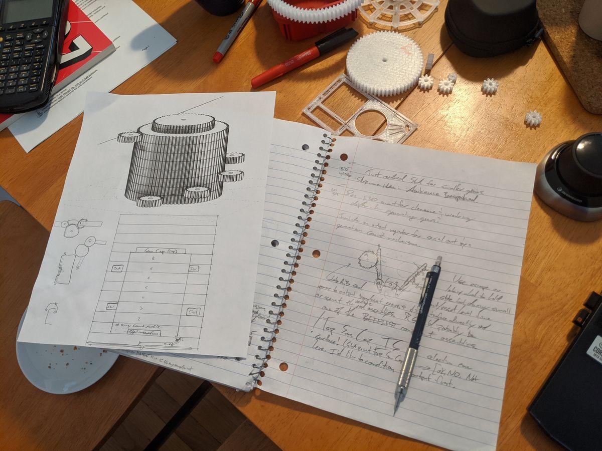
Eventually a much faster, more dynamic design came to me for what has become known as a "counting transmission". Let's point our CAD and 3D printer at it.
Stacked compound planetary geartrains
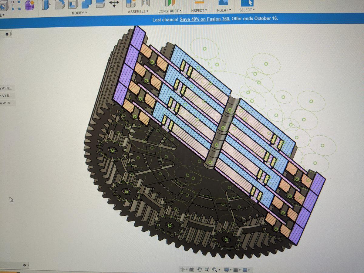
One can not fear the part count when on the heels of a usable solution. Ok, part count certainly is an issue when a project needs to scale the way GOL does, but we're in a flow-state, so let's flow.
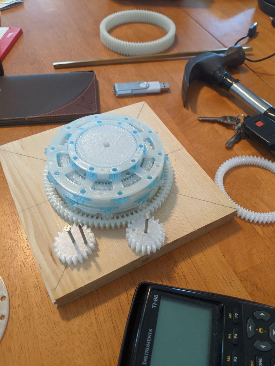
A counting transmission layer, full size
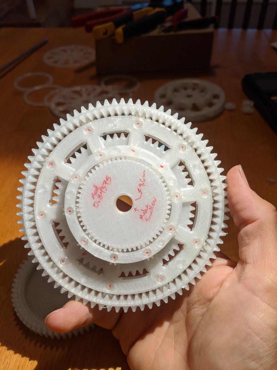
One layer of a counting transmission assembled at full scale, printed in filament. Not long after achieving this point, I began looking for a way to make the parts smaller and therefore more quickly.
Another new way to work
So, maybe if I reduce the size of the parts I can make more of them faster, and then I'll be able to test this counter, which is one of two cruxes of designing a mechanical Game of Life. You can't filament print gears as small as I desired. You can't resin print gears that small either because the support material is many times larger than the width of the tiny gear teeth (learned quickly from experiments). We need a mold. We are going to build a mold, and we are going to cast resin gears. Here we see what appears to be a usable master pattern for casting a silicone mold that will be used for casting a special engineering resin into tiny gears and parts. Simple. Once this works, we can produce entire assemblies in a single batch, which will be much faster than having a filament printer do the work of producing parts.
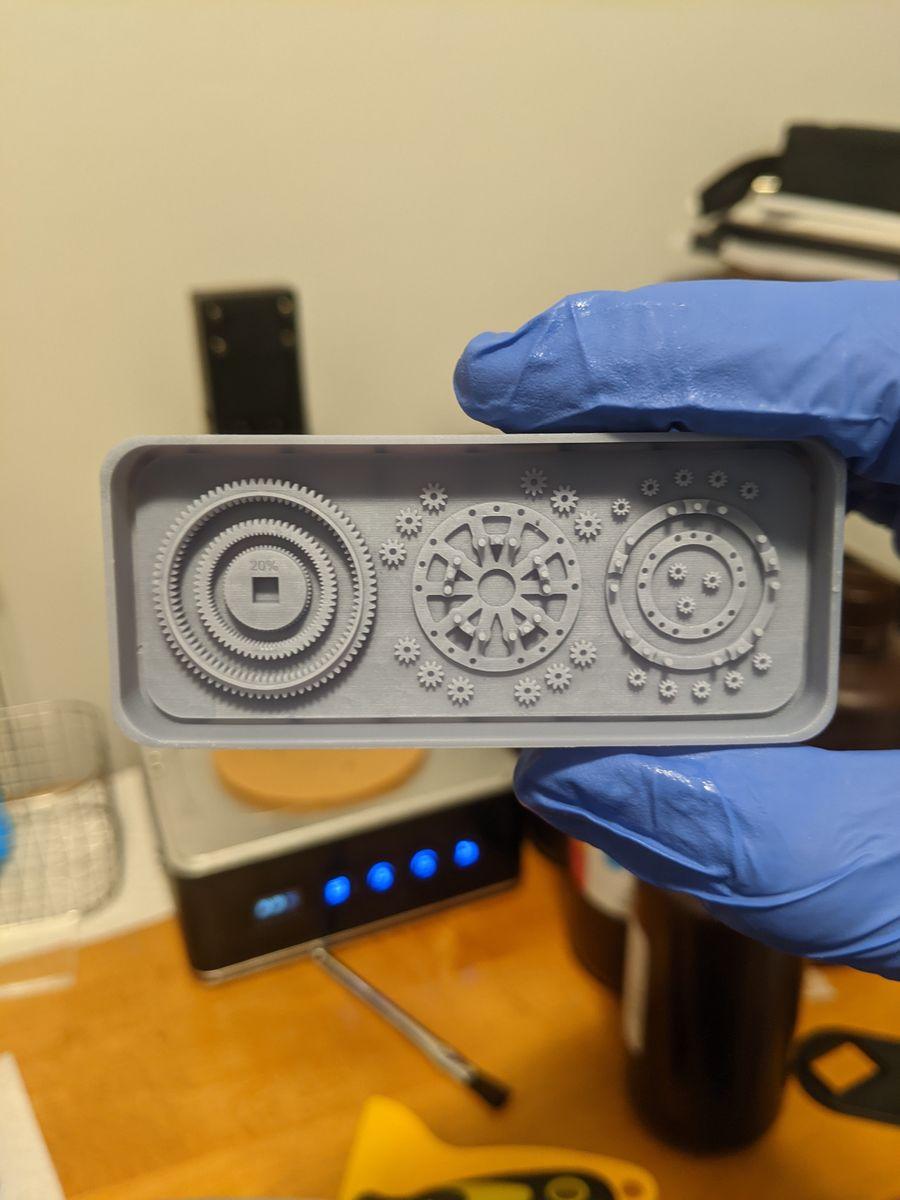
Ok, not quite
Some adjustments need to be made.
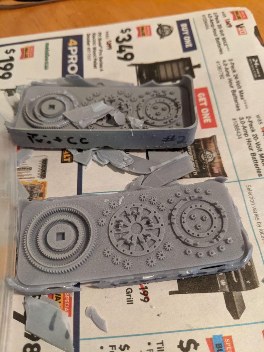
First parts pulled
I used plexiglass as the back half of the mold, and that was not the right move. The next mold design will accept a custom silicone back.
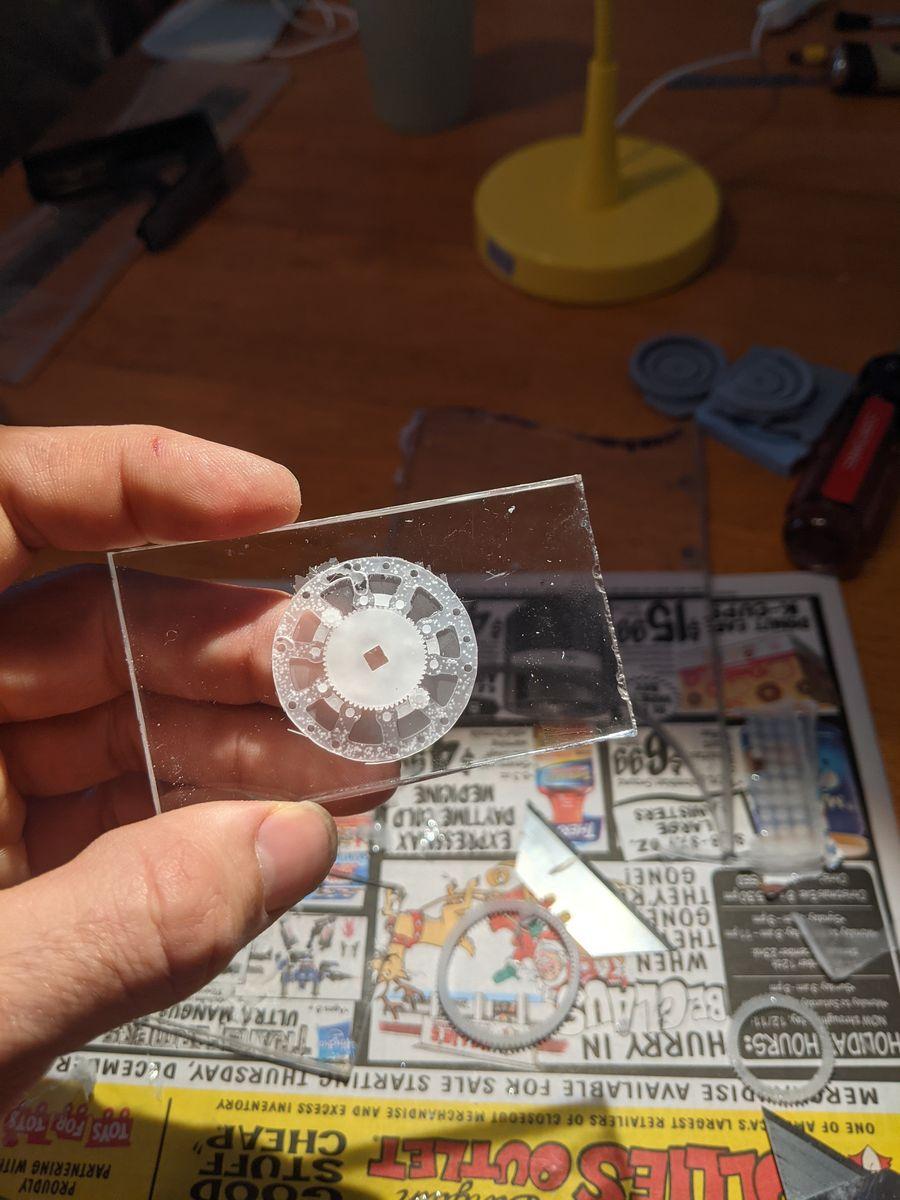
Usable parts mold
After some experimentation, we have what should produce some usable parts for us. Additionally, the scale has been decreased further to what is probably the limit when considering how the resin printer's mask resolution will affect the meshing of such small gears.
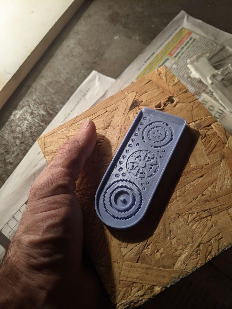
Voila!
After a lot of experimentation, we see a successful run of parts, and a successfully assembled small-scale, all cast-resin gear assembly.
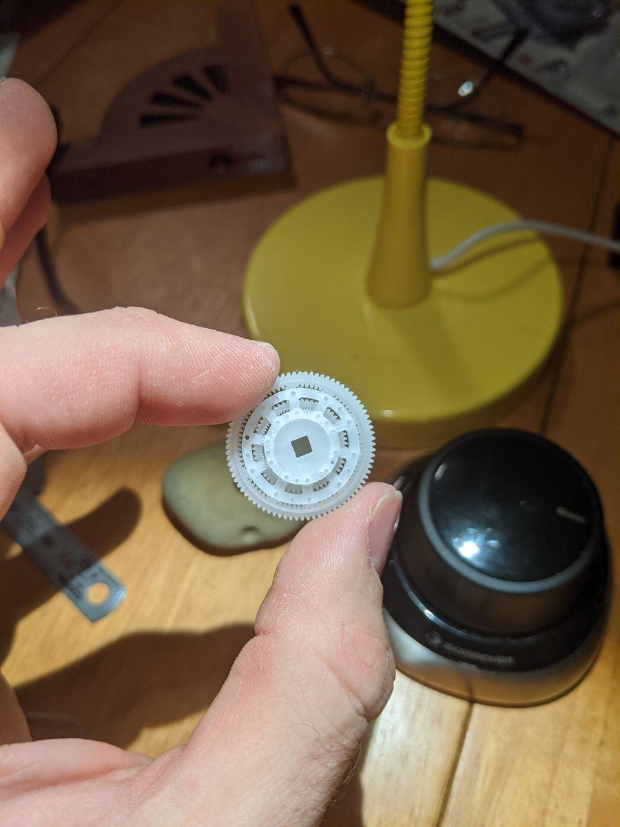
Tiny parts make tiny work
Although we can, in fact, run an entire set of parts in one casting session, there turns out to be a caveat. At this scale (pictured here beside a quarter) all of the time saved in time-to-parts seems to vanish into the extremely difficult task of assembling the component. Assembly requires tweezers and not breathing on anything at all while you work.
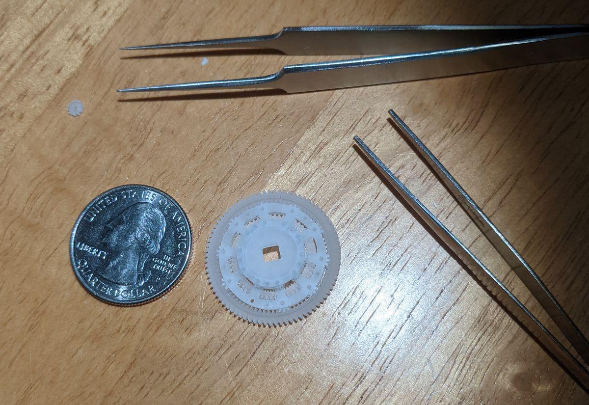
The happiest size
Given the constraints associated with having to assemble the mechanisms myself, I settled on continuing my prototyping at 60% scale from the original design. At this scale, I could design certain parts to be made from resin molds while the filament printer built the parts it was better suited to. In this way I could most efficiently run at the highest utilization of the printer + casting runs + resin-printed parts.
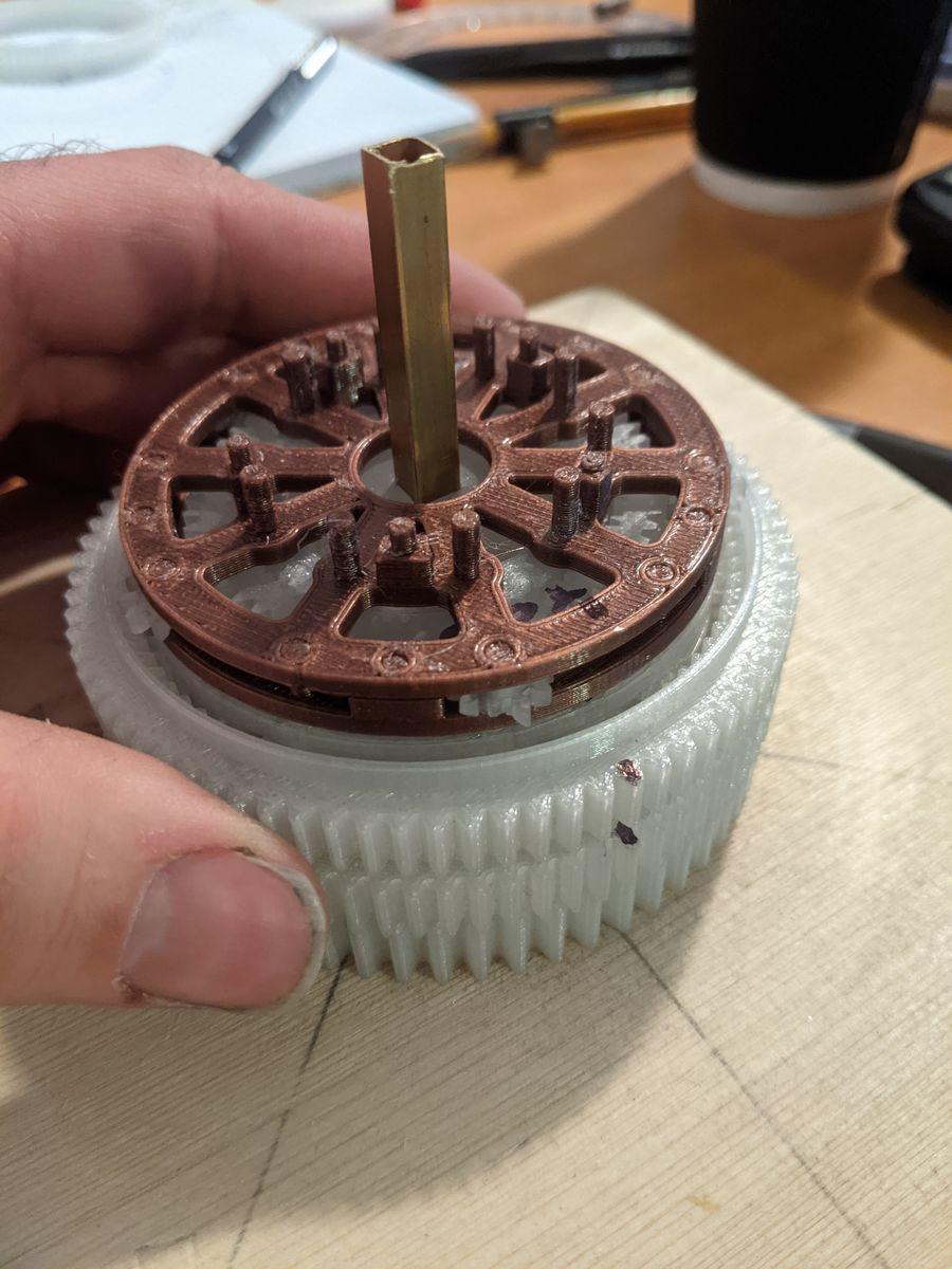
I’ve set work on Hello World down for now, but am keen to pick it back up in the near future. Since last working on the project, I have gained experience in other means of production and philosophies of design. Furthermore, the technology of the maker and engineer is constantly improving, both in material properties, accessibility and intelligence.
The work was never wasted: the casting and small-part molding I worked out in this last stretch are exactly what allowed me to approach an acquaintance to revisit a problem they’d shared with me nearly 4 years earlier. Check out my work on the Celestaphone. Skills from one bench rarely stay on one bench.